
Executive Summary: The Cloud Architecture Blueprint
Cloud infrastructure architecture is the engineering discipline of designing, assembling, and orchestrating distributed computing components—virtual compute nodes, storage volumes, software-defined networks, load balancers, and managed databases—into a coherent, resilient, and cost-effective digital platform.
Amateur cloud deployments treat the cloud as nothing more than a hosted virtual machine farm. By contrast, professional Cloud Infrastructure Architecture embraces cloud-native principles: decoupling state from compute, eliminating single points of failure through multi-availability zone redundancy, enforcing least-privilege network isolation via Virtual Private Clouds (VPCs), and codifying all infrastructure declaratively via Infrastructure as Code (IaC).
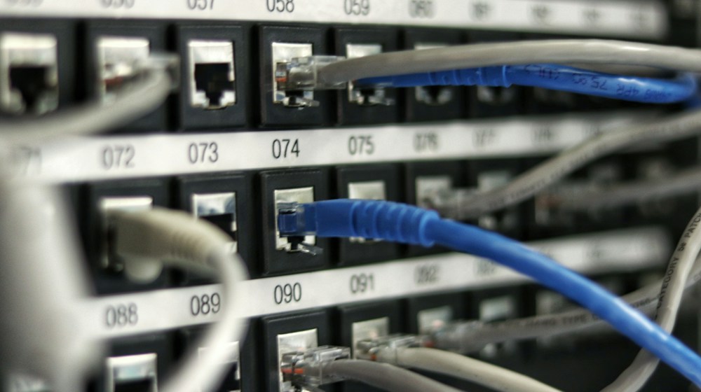 Figure 1: Production Multi-Tier VPC architecture: Public subnets, Private application tiers, and Isolated database enclaves.
1. The Virtual Private Cloud (VPC): Software-Defined Isolation
The foundational security boundary of any enterprise cloud environment is the Virtual Private Cloud (VPC). A VPC is a logically isolated virtual network dedicated to your cloud account, completely insulated from other customers on the hyperscaler’s physical hardware.
The Standard Three-Tier Subnet Topology
An enterprise-grade production VPC divides its assigned IPv4 CIDR block (e.g., 10.0.0.0/16) into three distinct functional subnet tiers spread across at least two or three Availability Zones:
+-----------------------------------------------------------------------------------+
|                        PRODUCTION VPC (10.0.0.0/16)                               |
+-----------------------------------------------------------------------------------+
| [ TIER 1: PUBLIC SUBNET (10.0.1.0/24) ]                                           |
|   - Connected to Internet Gateway (IGW)                                           |
|   - Hosts: Application Load Balancers (ALBs), NAT Gateways, Bastion Hosts         |
|   - Direct inbound and outbound public internet routing                           |
+-----------------------------------------------------------------------------------+
| [ TIER 2: PRIVATE APPLICATION SUBNET (10.0.10.0/24) ]                             |
|   - NO Direct Inbound Internet Access                                             |
|   - Outbound internet routed via NAT Gateway in Tier 1 (for package updates)      |
|   - Hosts: Kubernetes worker nodes, microservice containers, application runtimes|
+-----------------------------------------------------------------------------------+
| [ TIER 3: ISOLATED DATABASE ENCLAVE (10.0.20.0/24) ]                              |
|   - ZERO Internet Access (No IGW, No NAT Gateway routing)                        |
|   - Communicates ONLY with Tier 2 application nodes via strict security groups    |
|   - Hosts: PostgreSQL / MySQL database clusters, Redis caches, sensitive vaults   |
+-----------------------------------------------------------------------------------+
Security Groups vs. Network Access Control Lists (NACLs)
- Security Groups (Stateful): Act as virtual firewalls at the individual instance/network interface level. If you allow inbound traffic on port 443, return traffic is automatically permitted, regardless of outbound rules.
- Network ACLs (Stateless): Act at the subnet boundary level. Rules are evaluated sequentially (Rule 100, Rule 200). Inbound and outbound rules must be explicitly and symmetrically defined.
2. Load Balancing and High-Availability Clustering
A single server is a single point of failure. Cloud architecture achieves high availability by distributing traffic across pools of redundant instances using Elastic Load Balancers (ELBs):
 Figure 2: Microservice orchestration: Ingress controllers distributing traffic to auto-scaling container pods.
- Application Load Balancers (Layer 7): Inspect HTTP/HTTPS headers, cookies, and URL paths. They route traffic intelligently—for instance, sending
/api/v1/checkoutrequests to the checkout microservice cluster, and/static/*requests to an object store or CDN. - Network Load Balancers (Layer 4): Operate at the transport layer (TCP/UDP). Engineered for ultra-high throughput and sub-millisecond latency, capable of processing tens of millions of concurrent requests per second without terminating TLS.
- Autoscaling Groups (ASGs): Continuously monitor operational metrics (CPU utilization, memory pressure, request queue depth). When traffic spikes, the ASG automatically launches additional instances across availability zones, registers them with the load balancer, and shrinks the fleet when demand subsides.
3. Storage and Database Architectural Patterns
Enterprise applications require different storage abstractions depending on I/O characteristics:
| Storage Class | Cloud Primitive | Access Protocol | Typical Workload Profile |
|---|---|---|---|
| Block Storage | AWS EBS, Azure Managed Disk | NVMe / iSCSI block protocol | High-performance OS boot disks, active transactional databases |
| File Storage | AWS EFS, Google Cloud Filestore | NFSv4 / SMB network protocol | Shared content management systems (WordPress), shared dev directories |
| Object Storage | AWS S3, Google Cloud Storage | HTTPS REST APIs (GET/PUT) | Media assets, data lake analytical corpora, immutable backup archives |
| NoSQL / KV | DynamoDB, Cloud Bigtable | Specialized SDK RPC calls | Ultra-fast user session storage, shopping carts, IoT telemetry |
4. Infrastructure as Code (IaC): The Discipline of Repeatability
 Figure 3: Declarative Infrastructure as Code (IaC): Provisioning repeatable, version-controlled cloud topologies.
Configuring cloud resources through manual clicking in web consoles (pejoratively termed “ClickOps”) is an anti-pattern in professional engineering. Manual configurations cannot be audited, cannot be peer-reviewed, and lead to catastrophic configuration drift.
Modern cloud architecture is built upon Declarative Infrastructure as Code (IaC) using tools like Terraform, OpenTofu, AWS CloudFormation, or Pulumi:
- Version Controlled: Cloud architecture manifests live in Git repositories alongside application source code. Every modification to a firewall rule, database instance size, or subnet routing table undergoes code review and automated linting.
- Idempotency: IaC engines calculate the state difference between the declared code and the real-world deployed cloud infrastructure, making only the necessary API calls to reconcile drift.
- Disaster Recovery Replication: If an entire cloud region experiences an unprecedented catastrophic outage, an identical, production-ready environment can be stood up in an alternate region in under 15 minutes by executing a single automated pipeline:
terraform apply.
5. The Well-Architected Framework: The Five Pillars
Hyperscalers evaluate cloud architectures against the industry-standard Well-Architected Framework:
- Operational Excellence: Running and monitoring systems to deliver business value and continually improving processes (automated observability, runbooks).
- Security: Protecting information and systems (Zero Trust, least privilege, data encryption at rest and in transit).
- Reliability: The ability of a workload to perform its intended function correctly and consistently, recovering automatically from disruptions.
- Performance Efficiency: Using computing resources efficiently to meet requirements as demand changes (right-sizing compute, caching at the edge).
- Cost Optimization: Avoiding unnecessary costs and continuously eliminating unutilized capacity through FinOps practices.
Conclusion: The Resilient Cloud Enterprise
Cloud infrastructure architecture is not a passive checklist of servers; it is a dynamic, living system designed to withstand catastrophic failure without human intervention. By embracing strict network segmentation via multi-tier VPCs, deploying resilient load balancing and autoscaling fleets, and managing all assets through version-controlled Infrastructure as Code, modern engineering teams build systems capable of scaling to hundreds of millions of users with rock-solid, five-nines (99.999%) availability.
Disaster Recovery Patterns, RPO, RTO, and Multi-Region Architectures
High-availability enterprise systems are engineered to withstand complete physical data center outages, subsea cable severances, and localized power grid collapses. Building resilient infrastructure requires quantifying business tolerances through two fundamental metrics: Recovery Point Objective (RPO) and Recovery Time Objective (RTO).
Quantifying Disaster Tolerances
- Recovery Point Objective (RPO): The maximum acceptable data loss measured in time. An RPO of zero means no transactional data can be lost during an outage; an RPO of four hours allows restoration from a backup snapshot taken four hours prior.
- Recovery Time Objective (RTO): The duration of time permitted to restore full business service following an incident declaration. Low RTO systems require automated failover mechanisms that restore traffic within seconds.
+--------------------------------------------------------------+
|             Spectrum of Disaster Recovery Strategies          |
+--------------------------------------------------------------+
| [Backup & Restore]  --> RPO: Hours/Days  | Cost: Minimal      |
| [Pilot Light]       --> RPO: Minutes     | Cost: Low          |
| [Warm Standby]      --> RPO: Seconds     | Cost: Moderate     |
| [Active-Active]     --> RPO: Real-Time   | Cost: High         |
+--------------------------------------------------------------+
Four Multi-Region Architectural Strategies
- Backup and Restore: Regularly shipping encrypted block storage snapshots and database dumps to an offsite secondary region. While highly cost-effective, recovering full production workloads from cold backups can require hours or days of provisioning time.
- Pilot Light Architecture: Maintaining core data replication in a secondary cloud region while leaving compute instances turned off. In a disaster event, automation scripts provision auto-scaling groups and spin up application servers around the live secondary database replica.
- Warm Standby (Scaled Down): Operating a fully functional duplicate application stack in a secondary region running at minimal capacity (e.g., a single small instance per tier). During primary region degradation, DNS traffic is redirected and the secondary cluster scales out horizontally.
- Active-Active Multi-Region Mesh: Running active workloads across multiple global regions simultaneously. Anycast BGP routing and Geo-DNS dynamically route users to the lowest latency healthy region. Data synchronization requires globally distributed, distributed-consensus databases (such as Google Cloud Spanner or AWS DynamoDB Global Tables) capable of resolving write conflicts across global distances.
Infrastructure as Code (IaC) and Drift Detection
Modern cloud reliability relies upon treating infrastructure entirely as code. Storing declarative configurations in version control systems (Git) allows teams to reconstruct entire multi-region data center topologies programmatically within minutes. Automated drift detection pipelines continuously compare live cloud resource states against Git-committed state files, automatically alerting engineers or rolling back unauthorized out-of-band manual changes made via administrative consoles.
Continuous Verification and Chaos Engineering in the Cloud
Modern cloud architecture mandates continuous verification through chaos engineering practices pioneered by Netflix’s Simian Army. Rather than waiting for unpredictable hardware degradation or network partitions in production, engineering teams proactively inject controlled failures into their environments using tools like Chaos Mesh or Gremlin:
- Latency Injection: Simulating subsea cable packet degradation to verify timeout thresholds across microservice boundaries.
- Instance Termination: Randomly terminating compute nodes in non-production environments to guarantee that auto-scaling groups and health checks self-heal autonomously without dropping active user sessions.
- Regional Blackhole Testing: Simulating total loss of an entire cloud availability zone to validate multi-zone failover mechanisms under realistic high-load conditions.


Cloud Computing Explained: A Complete Beginner's Guide
A comprehensive guide to cloud computing, breaking down IaaS, PaaS, SaaS, public vs private clouds, hypervisor virtualization, and cloud economic models.
AWS vs Microsoft Azure vs Google Cloud: Understanding the Differences
A comprehensive comparative analysis of the Big Three hyperscale cloud providers, evaluating compute services, storage performance, AI ecosystems, pricing models, and enterprise fit.

What Is Serverless Computing and How Does It Work?
A deep dive into serverless architecture, event-driven execution models, Function-as-a-Service (FaaS), cold start optimization, and the economics of paying zero for idle infrastructure.